W Bends
Overview
W-Bending, also known as “Back Bending” is a technique used to form deep U- shaped profiles without the need for specialized tooling.
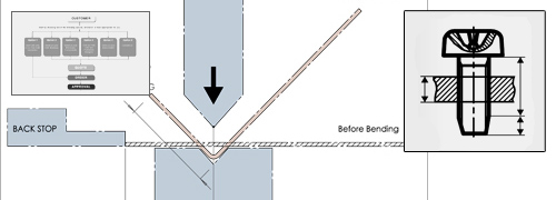
This works by first forming a slight bend in the middle of the part, then forming the side bends to create a W-shape. The slight bend in the middle is then flattened back to form a U-shape.
Previously, profiles with a deep U-shape have had to be separated into two parts, and then welded together to create the U-Shape profile. W-Bending is an excellent replacement for this process, so long as the part requirements and dimensions meet the constraints outlined below.
Materials
Currently, we offer W Bending as a tested process for our following stocked 5052- H32 Aluminum:
We are in the process of testing W-bending with our other stocked materials to
determine which materials can guarantee a quality end-result.
If you require a deep U-Shape profile in another type of material, contact us to
discuss your options.
| Gauge | Thickness | Thickness Tolerance |
|---|---|---|
| 8 gauge | (0.1285" | 3.26mm) | ± 0.007 | ± 0.18mm |
| 10 gauge | (0.102" | 2.59mm) | ± 0.006 | ± 0.15mm |
| 11 gauge | (0.091" | 2.31 mm) | ± 0.0045" | 0.114mm |
| 12 gauge | (0.081" | 2.06 mm) | ± 0.0045" | 0.114mm |
| 14 gauge | (0.064" | 1.63 mm) | ± 0.0040" | 0.102mm |
| 16 gauge | (0.051" | 1.30 mm) | ± 0.0035" | 0.089mm |
W Bends Examples


.jpg)


Constraints
The following dimensional constraints for U-shaped profiles should be taken into account to ensure proper clearances for our machines and tooling.
Maximum length = 35.875” (911.225mm)
Minimum recommended width = 3.75” (95.25mm)
If the height is less than 2.5x the width, the maximum height is 23”
(584.2mm)
If the height is more than 2.5x the width, the maximum height is 13.5” (342.9mm)
Flattening the W-bend may increase dimensions measured across it by up to +0.010” (0.0254mm); standard bending tolerances must be taken into account for the side flanges as well.
The flattening process for the W-bend is not perfect, a slight +/-1° bend may remain after flattening
Parts cannot have flanges crossing the W-bend. Cutouts on the same face as the W- bend may become distorted if they’re too close to the W-bend. As a result, it’s recommended to keep cutouts about 0.750” (19.05mm) away from the middle of the face. However, cutouts centered across the W-bend should have only minor distortion.

Finishing Constraints
The W-bending process will leave a crease in the part from the process of flattening the W-bend. This crease is most visible on the outside of the part.
While it’s possible to buff out the crease somewhat, it may still be visible. Buffing out the crease may thin the material below its thickness tolerance.
Powdercoat is recommended to reduce the visibility of the W-bend crease. Textured powdercoat is ideal for minimizing the visibility of the crease. We do not recommend glossy powdercoat, as it can make the crease much more visible.
Grained finish is another option to reduce the visibility of the crease, however the buffing & re-graining required often results in the material being thinned below its standard thickness tolerance around the crease.
Finishes Examples


